LOCATING & ENGINEERING HYDROLOGICALLY
SECURE HLW REPOSITORIES
A Proposal for Disposal of the United Kingdoms High Level
Nuclear Wastes in Sub-Seabed Reservoir Repositories
Timothy H. Watts
C.M.A. International Ltd.
You are visitor number : your email comments will be welcome at: cmainternational@hotmail.com
EXECUTIVE SUMMARY
The problem of how to dispose of high level nuclear waste has yet to be solved. There are many unanswerable questions about mined repositories, not least the problem of water flow and hydrology in temperate climates. A solution is proposed here by which depleted oil and gas fields could be used as waste repositories. Offshore oil and gas reservoirs would be re-engineered and managed remotely using technologies adapted from the exploration and production industry. Once in place, ceramic nuclear wasteforms would be cemented into steel lined wells, backfilled and cooled initially using passive convection loops. The repositories would then be closed and the reservoirs returned to the geologically stable and hydrologically secure closed systems they have been since hydrocarbons migrated into them millions of years ago.
This paper was first published in the Proceedings of the Third European Engineering Geology and 33rd Engineering Group, Geological Society, Annual Conference, September 1997, Newcastle University. The disposal technology is covered by United Kingdom patent number 2286284B.

INTRODUCTION
Finding a solution for the permanent disposal of heat generating radioactive waste and spent reactor fuel is one of the great challenges facing mankind. At present all high level waste is stored for cooling off, awaiting an answer to the problem. This paper outlines the main difficulties of current nuclear high level waste (HLW) disposal technology and proposes a solution by transferring experience, technology and facilities, gained from the offshore drilling industry.
All approaches to deep radwaste disposal are constrained by local climate and geology; this proposal is no different. Within the context of the United Kingdom's own jurisdiction, see appendix 1, the proposal aims to produce the best workable engineering solution and the most environmentally safe option for HLW disposal. Solving the HLW disposal problem is for the benefit of future generations, hence the cost of implementation has not been a determining factor in this design, however all the technology referred to here, is either in use, under development or can be re-engineered.
MINED REPOSITORIES
Igneous rock masses, particularly granite have been the favoured rock type in most HLW repository designs, having great rock strength, low porosity and high thermal conductivity. Sadly however, granites also have extensive joint systems that can extend to great depths. Fracture zones in metamorphic terrain extend over many kilometres. The exact characterisation of these features at depth is therefore very difficult. The Hot Dry Rocks (HDR) project designed to investigate the potential of geothermal power in the Carnmenellis granite in Cornwall, ran into difficulty because of the inability after fourteen years research to predict the hydrological behaviour of natural jointing. The joints in this locality are believed to extend far below the 2.5 kilometres depths drilled to date and it was suggested that only by drilling to 6 kilometres could these characteristics be resolved (Parker 1991). Granites can act as prolific aquifers with flow not just confined to joints. Feldspar degradation can lead to the development of high permeability. Fractures in metamorphic and igneous rock bodies can act as significant conduits in saturated rock. The rejection of planning permission for a Rock Characterisation Facility (RCF) at Sellafield in 1997 illustrates uncertainties of predicting the hydrology of a fine grained igneous rock mass, (RWMAC, 1994).
A hydrological baseline response must always be established when siting a mine or excavation. This is required because of the mechanical disruption caused both by the mining itself and the long term influence on local ground water patterns and aquifer regimes caused by changed flow patterns. In the case of a nuclear repository, the hydrological baseline may never be drawn because of unknown climatic changes in the future. Wherever there is a meteoric component to the hydrological regime, there is a potentially oxidising subsurface environment. Under such conditions the chances of material corrosion plus movement of radionuclides and secondary products in solution, is greatly increased. Unless there is a completely sealed hydrogeological regime or a proven connate water system, there is no guarantee of hydrological containment. Unfortunately the nearer the surface a repository is sited in temperate latitudes, the greater the risk that oxygenated water will circulate in the vicinity and eventually contribute to breaching the engineered repository barriers.
It is government policy to store HLW to allow cooling for fifty years. Although this should be ample time to find a solution to the disposal problem, in the meanwhile it merely creates a lag from which time onwards waste will still need to be disposed of on a continual basis because it is produced today on a continual basis. If HLW is not disposed immediately as it comes out of cooled storage, building a single vault type or mined repository to accommodate all the waste arising means the repository must remain open for yet another fifty years until the current un-cooled HLW is available and ready for disposal. This presents great management problems for long term planning, operations and financing. Most importantly, a single disposal site defers the problems for future generations to deal with because the current HLW repository designs apply a batch system solution to what is a continuous waste production problem. Mined repositories in saturated rocks must be continually pumped for the shafts and tunnels to remain accessible during emplacement. Similarly contaminated water must be also be disposed of over the fifty year emplacement programme. There exists the possibility that if any of the waste starts to leak prematurely, the entire facility would have be sealed before its due date.
For mined repositories the need for a structurally coherent geology to allow excavation is paramount. Using deep drilling technology however, once the boreholes are drilled and cased, the need for great rock strength is no longer an issue. All that is required for a drilled repository is a hydrologically secure location. If the pore water cannot move, neither will the rock.
WASTE VOLUME
The volume of vitrified waste produced from the Magnox reactor programme by 1993 was 61m3, a volume projected to grow to 860m3 by the year 2010, (Radioactive Substances Division, 1994). With commitments to manage waste arising from overseas contracts through THORP, the total volume of UK vitrified waste will be 3830m3 by the year 2030.
Developments in deep drilling technology over the last decade have greatly increased the rock sections that can be accessed through flat lying geological formations. This has been achieved by drilling and completing wells horizontally. Not only does this allow far longer homogenous reservoir sections to be produced, the volume of cased well bore within a characterised reservoir section, is now increased by one or even two orders of magnitude. Where previously, only a 30 metre section of producing formation might typically have been available to complete, representing the vertical section through a reservoir; currently 1000-3000m sections are being developed horizontally and even inclined upwards and steered laterally. Sometimes branches are drilled from the main borehole. Such well completions are known as multilateral wells. This increases the bore hole volume available within a finite and homogenous fluid system (reservoir unit), so it has now become possible to consider the economic potential for utilisation of these resources for toxic and radioactive waste, once hydrocarbons are depleted.
Currently it is possible to drill and case off a well with a 3 kilometre horizontal section. It is also possible to drill boreholes wide enough to accommodate solid wasteforms with a diameter of 15 cm. These wells can be guided through geological formations that are only 2-3 metres thick in formations 6-7 kilometres away from the location of the platform. Wider and longer well bores are currently being planned. The entire UK HLW inventory and arisings to the year 2030 can theoretically be accommodated in a limited number of fields.
Table1: Potential reservoir waste volume available using exisiting technology
|
borehole diameter |
wasteform diameter |
repository section |
section volume |
buffered volume |
fields required |
heat output |
|||||
|
(ins) |
(ins) |
(m) |
(m3) |
33% per well (m3) |
|
(kW) |
|||||
|
6 |
2 |
2000 |
4 |
1 |
162 |
41 |
|||||
|
8.5 |
4 |
2000 |
16 |
5 |
40 |
162 |
|||||
|
8.5 |
4 |
3000 |
24 |
8 |
27 |
243 |
|||||
|
12.25 |
5.5 |
1000 |
15 |
5 |
43 |
153 |
|||||
|
12.25 |
5.5 |
2000 |
31 |
10 |
21 |
307 |
|||||
|
12.25 |
5.5 |
3000 |
46 |
15 |
14 |
460 |
|||||
|
17.5 |
11 |
1000 |
61 |
20 |
11 |
613 |
|||||
|
17.5 |
12 |
3000 |
219 |
73 |
3 |
2189 |
|||||
|
|
waste volume |
|
heat ouptut |
|
wells per |
|
|||||
|
|
2030 AD (m3)** |
|
per kW/m3 * |
|
field |
|
|||||
|
|
3280 |
|
2 |
|
15 |
|
|||||
|
**source: |
Radioactive Substances Division, DOE/RAS/RW 92.010 |
||||||||||
|
* source: |
Radioactive Substances Division, DOE/RAS/RW 93.005 |
||||||||||
RESERVOIR REPOSITORIES
Geology
Sandstone repositories
The migration of hydrocarbons is governed by simple buoyancy and hydrodynamic principles, moving from source rock shales to reservoir sandstone and limestone formations. Flow through permeable conduits is governed by fluid pressure gradients and can occur over periods covering of millions of years. Hydrocarbons can either by discrete diffusion or in conjunction with formation water flow. The study of the hydrodynamics of formation waters gives a reasonable idea of the migration route for hydrocarbons. Once trapped, a multiphase liquid system of water and either oil, gas or both exists, until the thermodynamics or structure of the hydrocarbon accumulation change, allowing either expansion and dissolution of gas through biodegradation of oil on uplift, or by heating and further hydrocarbon cracking with burial. In the North Sea most hydrocarbon migration took place between the late Cretaceous and the Miocene.
Oil and gas fields do not generally lose their structural or hydrological integrity when they become depleted. By careful management during production, pressure is maintained by re-injecting produced gas at the top of the reservoir where possible, and the hydrology is stabilised by re-injecting produced water beneath the oil or gas/water contact. This husbandry of hydrocarbons means when a field approaches the end of its useful economic life it is still hydrologically intact. Pressure eventually drops even where gas injection has taken place in a reservoir but this has positive advantages for implementing a waste disposal programme that will eventually elevate the temperature and therefore pressure in the reservoir again. The Rough Field was used as storage facility receiving gas pumped from other fields to maintain pressure in the British Gas pipeline grid onshore.
To illustrate how stable and yet elastic some oil fields are it is helpful to examine the Magnus Field in the Northern North Sea. The Magnus field is a deep sea clastic fan, with a pore volume of 2706 m3. It is sealed by a major rotational fault system and unconformable upper Cretaceous shales. The field is unusual because the pore water system remained static until oil migrated into the structure, 35 myr after the structure formed, (Macaulay et al., 1992). A decade of oil production has resulted in a drop in the reservoir pressure by at least 200 bars. This represents a field wide change in the Poisson's ratio of 8% (Watts et al, 1996) and a change from being a substantially over pressured (1.5 bar/m3 ) reservoir, to one that is now considerably under pressured (0.65 bar/m3 ). Despite this change, oil production continues with no evidence of sea bed collapse or external hydrocarbon leakage. Minor internal fracturing is assumed to have occurred due to the injection of cold sea water but otherwise the reservoir retains its integrity having undergone temperature and fluid phase changes for the last fifteen years.
There are some locations which are undergoing active migration and leakage today. Reservoirs formed in the upper Cretaceous Chalk, such as the Valhall field are typical of this category. Such fields must be avoided because of their active fracture systems, which can extend to the seabed as evidenced by the gas cloud on seismic sections across the Valhall field, or the rapid collapse of the chalk porosity after oil production as seen by the sea bed collapse in the case of the Ekofisk Field.
The best sites for reservoir repositories are in quiescent areas where production has not affected the reservoir architecture or comprised sealing integrity. Turbidites are good candidates for reservoir repositories because they are not necessarily connected directly to a regional aquifer system.
Having contained liquid and gaseous hydrocarbons for millions of years under pressure, sometimes approaching lithostatic pressures, oil and gas reservoirs are proven sealed systems with respect to the fluids they contain. Long term geological stability and hydrological security is guaranteed. Provided the reservoir retains its integrity, there is no need base a safety case entirely on the probability of containment being breached.
Disposal into Shale
Although the permeability of shale is very low compared to sandstone, its mechanical properties make the geometry and behaviour of fractures initiated either during the drilling process or on subsequent heating after waste emplacement, difficult to model. The encasing shale is not a finite body compared to the sandstone reservoir, shale fractures may be of limited extent, but they may also extend over many metres and connect with a pre-existing open fracture systems elsewhere. Experience gained through disposal of large volumes of ground up rock from deep drilling processes through injection of slurries into specially fractured wellbore intervals, shows it is far more effective to inject into shales, which can support large waste volumes through induced fracture systems that run for hundreds of metres away from the wellbore, than sandstone which tends to plug up and heal. Fractures induced in a sandstone reservoir do not generally lead to the loss of reservoir fluids elsewhere from the system. The integrity of a reservoir undergoing internal dislocation or microfracturing is maintained by the elasticity of the encasing shales or salt plasticity, as can be seen in the cases of Magnus and Rough fields. The effect of internal fracturing within the reservoir is thus accommodated over the whole system with little or no net change on the integrity of the reservoir as a whole.
Turbidites
Typically deep water clastic reservoirs are formed by turbidity or mass flow deposits in slope-fan or basin-floor fan settings. Sandy mud flows are triggered by periodic seismic events or slope failure. This causes slides, slumps, debris flows and turbidity currents which are carried long distances underwater by a fluidised bed load driven under the force of gravity. Eventually the turbidity current stops depositing its bed load either as unconfined sandy basin-floor fan, a muddy overbank slope-fan deposit or as chaotic channel deposits. Sometimes multiple fans coalesce on the basin-floor, but often they are separated by some considerable distance, over 800km in the case of the Storegga Slide of northern Norway, (Shanmugam et al., 1995). Deep marine clastic reservoirs are bounded top and bottom by hemi-pelagic and pelagic shales. Thus turbidite sand bodies can become totally encased in impermeable or very low permeability shales, see figure 1.
Table 2: Potential Turbidite Reservoirs of the North Sea
|
Alba |
|
Balmoral |
|
Brae |
|
Britannia |
|
Claymore |
|
Forth |
|
Forties |
|
Gryphon |
|
Magnus |
|
Maureen |
|
Miller |
|
Montrose |
|
Nelson |
Mass flow or high density turbidity currents (Lowe, 1982) are often derived from previously deposited shelf edge sands, reservoir quality from such secondary deposition can result in clean and almost mono-mineralic assemblages. Bottom current or low density turbidity currents tend to result in more shaley reservoirs. Providing subsequent diagenesis does not occlude porosity, even shaley prone deep sea sands can provide good thinly bedded reservoirs.
Sub salt gas reservoirs
Gas from many of the fields in the southern sector of the North Sea has been trapped since its generation in the Cretaceous (Cornford, 1986). Despite more complex burial histories than the Northern North Sea turbidite fields, these salt sealed sandstones and dolomites of the Southern Permian Basin have remained intact and undisturbed for longer.
Location of potential reservoirs
Hydrocarbon reservoirs found within the boundaries of the United Kingdoms continental shelf fall into four main groups, I.) Palaeozoic clastics and carbonates, II.) Jurassic deltaic and deep sea clastic fan, III.) Cretaceous carbonates and IV.) Early Cenozoic clastics.
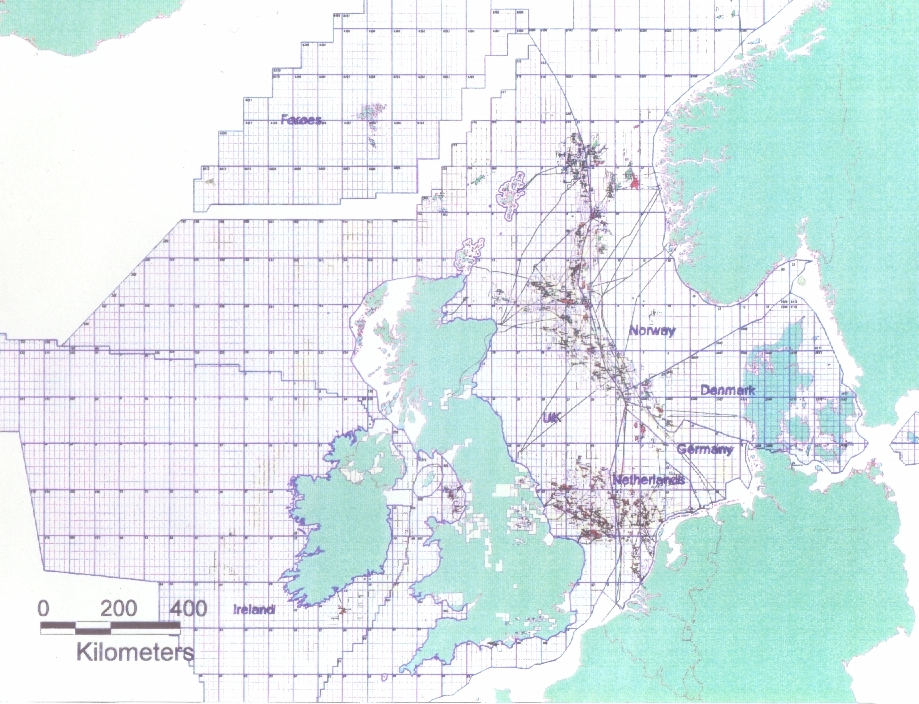
The North Sea is divided into two main hydrocarbon provinces, the Northern North Sea and the Southern Permian Basin, the former mainly oil producing and the latter only gas. The two are separated by the Mid North Sea High and the Ringkøbing/Fyn High. The other main hydrocarbon basins excluding onshore accumulations, are in the Irish Sea and to the west of the Shetland Isles extending out into the Atlantic towards Rockall.
Northern North Sea reservoir types
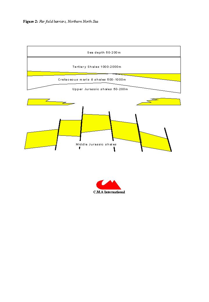
A typical Northern North Sea reservoir is the Brent Field. It is a shallow marine deltaic sequence formed by a series of major progradational sands. The Brent Group forms the main producing reservoir in many of the oil fields and is located along the spine of a major Permian graben system, an area known as the Viking Graben. A paleo triple junction is thought to connect the Viking Graben to the north with the Witch Ground Graben to the west and the Central Graben to the south, centred around 58o N and 2oE. The Brent delta prograded north from this junction during the Bathonian and Bajocian, forming fields such as Beryl, Brent, Ninian, Statfjord, Heather and Thistle. Sediment source was derived from reworked Lower Jurassic that were the result of upwarping of the triple junction. This basin inversion also mobilised marginal sands and deposited them in the East Shetland Basin at the far end of the Viking Graben. Most of the Brent type reservoir architecture is fault controlled, see figure 2.
The second major category of Jurassic reservoirs in the Northern North Sea, are formed from Oxfordian and Kimmeridgian fan sands. These fans represent mass flow deposits mobilised along the margins of the graben, activated after subsidence of the middle Jurassic deltaics during an Upper Jurassic marine transgression from the north. These upper Jurassic reservoirs consist of terrestrial and shallow marine turbidites, eg. Brae Field, or more typically shallow and deep marine sands, such as the Piper Field. Terrestrial deposits consist of coarse sands and conglomeratic debris flows which change laterally into turbidites and mass flow deposits in marine settings. In some cases secondary reworking of the initial debris flows into deeper quieter waters occurred, resulting in very fine quality sands in reservoirs such as the Miller Field, a reworked Brae sand in a distal environment. Typically these Upper Jurassic sands are inter bedded and frequently encased in Volgian and Kimmeridgian shale, the very same rock which provides the principle hydrocarbon source for most of the Northern North Sea. The architecture of upper Jurassic reservoirs is largely controlled by stratigraphy.
The next major reservoir group in the Northern North Sea are the Upper Cretaceous chalk fields, notably the Albuskjell, Dan, Ekofisk and Valhall fields. Extensive fracturing plus an active response to overburden pressure changes during production do not make these fields good candidates as repositories.
The final category of Northern North Sea reservoirs are the early Cenozoic sandstones which where deposited as the result of uplift and erosion of the East Shetlands Platform during the Palaeocene and Eocene. These sands flowed eastward over the axes of the main grabens, covering adjacent highs and forming a triangle with the apices at the end of the Viking, Central and the Moray Firth grabens. These fan and channel sands are laterally very extensive and are represented by fields such as the Montrose and Forties field, see table 2. They are some of the earliest fields developed in the North Sea and are those most likely to be abandoned in the near futures. A variety of fluid types are found in these early Tertiary fields, some like the Frigg field are gas filled, some are only partially filled because the reservoirs themselves were still forming structurally during the peak of oil generation in the Miocene.
Southern Gas basin type
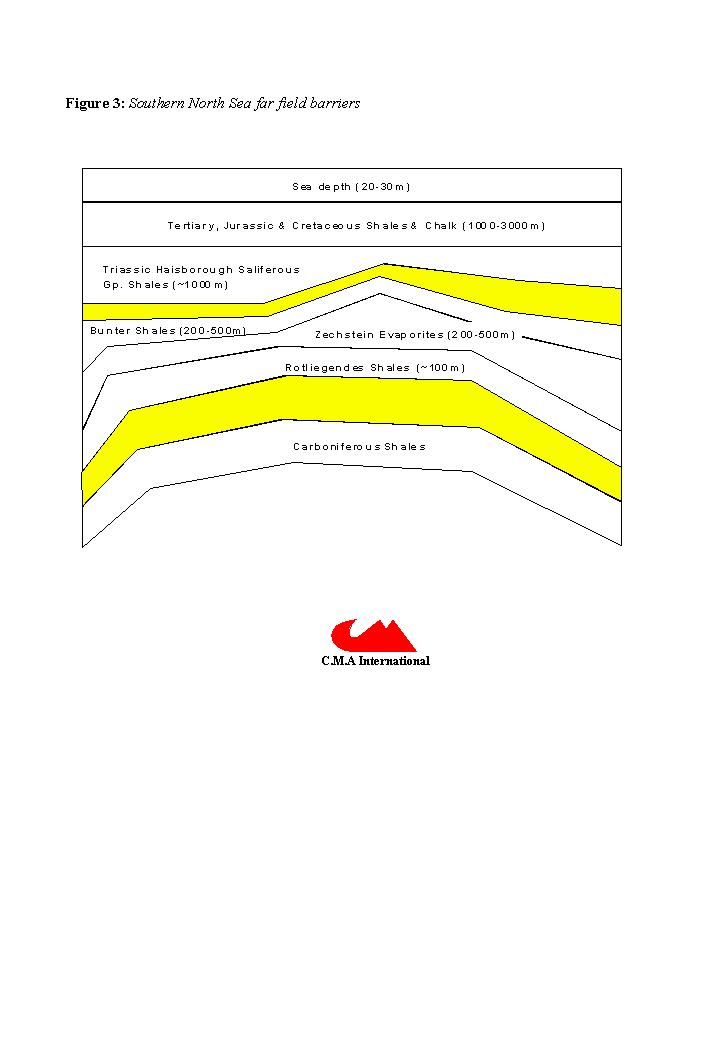
South of the Mid North Sea / Fyn Ringkøbing High, a completely different reservoir terrain exists. Here the Southern Permian Basin forms part of the giant gas province stretching across northern Europe, with hydrocarbons sourced from the Westphalian Coal Measures. These gas prone hydrocarbons are trapped stratigraphically in marginal Silesian sands or structurally in overlying Triassic sands, but most commonly, they sealed beneath the Zechstein salt at the centre of the basin in the Rotliegendes Sandstone, see figure 3.
Structurally the basin formed as the result of post-Variscan thermally induced crustal spreading (Glennie, 1986). Differential subsidence created a series of depressions such as the Broad Fourteens Basin and the Silverpit Basin, separated by terraces such as the East Midlands shelf and fault controlled highs like the Sole Pit and Clever Bank Highs.
In these basins the Carboniferous coal measures, lower Permian Rotliegendes sands and cyclical Zechstein carbonate and evaporitic sequences subsided.
The Rotliegendes Sandstone is the main sub-salt hydrocarbon reservoir. It consists of aeolian, fluvial and sabkha facies sands. Aeolian sands form the most important commercial reservoir zones such as the Leman Field. Peak gas generation occurred between late Jurassic and late Cretaceous times with inversion tectonics active in some areas well into the late Cretaceous and very early Tertiary. The Zechstein formed a seal over most of the Southern Gas basin, a seal which still retains its integrity due the ductility of the salt today, sealing any fault induced fractures. The majority of the sub salt gas reservoirs have therefore lain intact for the last 50 million years.
Irish Sea basin type
The principle reservoir found in the Irish Sea Basin is the Permo-Triassic Sherwood Sandstone Group. This group comprises of the St. Bees Sandstone Fm and the overlying Omskirk Sandstone Fm. Both reservoir sands are affected by significant diagenesis that governs their fluid regimes. Illite development in the Omskirk Sandstone (Woodward & Curtis, 1987) and silicification in the St.Bees Sandstone (Colter & Barr, 1975), has severely limited permeability. These formations are the primary reservoir for the main gas field in the Irish Sea, Morecombe Bay Field. This is a fault controlled reservoir which is gas filled, sourced from underlying upper Jurassic coals & marine shales (Bushell, 1986).
The Morecombe Bay Field is very shallow and the Irish Sea Basin is closely linked to the Cheshire Basin where the same formations are found. It is therefore unlikely that this area would constitute a potential HLW repository reservoir location.
Atlantic reservoir type
The territorial waters claimed by the UK out into the North Atlantic include very few known reservoirs because huge areas are currently un-drilled. The best known fields in this province include the Clair, Schiehallion and Foinaven fields. Reservoirs found in this province tend to be formed in the Tertiary. The Schiehallion & Foinaven reservoirs are both stratigraphic Cenozoic traps. Further exploration in the North Atlantic will possibly reveal some Mesozoic fields but to date the best possible exploration targets remain in the Cenozoic (Dore & Lundin, 1996) where large compressional features forming four way dip closures, are observed on seismic profiles.
WASTEFORMS
Glass
Vitrification in boron rich glass is the preferred option for the majority of Europe's liquid HLW inventory. The technology was first used at Marcoule in France and is currently used at Sellafield to stabilise HLW. It is moulded in stainless steel flasks and stored in air cooled vaults and water filled tanks. The casks are 40cm in diameter and stand about 130cm high, similar in appearance to large milk churns. The preferred option is to let these flasks cool for at least fifty years on site awaiting the eventual decision on their fate (Radioactive Substances Division, 1994). If a purely open minded approach to engineering the final solution for HLW is adopted, then the design of the containers and their current wasteform, with its fifty year old technology, should not be allowed to constrain the disposal criteria. The waste should be reprocessed into a wasteform and moulded in containers fit for purpose at the time the disposal programme starts. Present waste form and containers are designed to stabilise the waste with no regard to where it should go or how it should be handled.
Cement
Although the French and British governments prefer vitrification and have made large investments in this technology, the US government remains sceptical. Following thermal stability tests which required the temperature of radioactively fused glass to be reduced from 500oC to 150oC (Macy, 1993), thus increasing the volume of waste tenfold, the US has not endorsed vitrification as an appropriate technology. One of the wasteforms currently preferred in the US is immobilisation in cement. The advantages of these "low temperature ceramics" is simple technology and a chemical composition that can be tailored to the wasteform at ambient temperatures. This results in a material that is more resistant to leaching of Cs137 and Sr90 than glass. Cement can be easily poured or injected in-situ and the alkalinity of the material reduces the solubility and therefore mobility of plutonium and uranium.
Ceramic
Synroc is a titanate ceramic designed to immobilise radioactive elements and remain stable under high temperature in hostile geochemical environments, (Jostons, 1994). It is a synthetic basalt consisting mainly of zirconlite (ZrO2), hollandite (TiO2) and perovskite (Al2O3) which can be customised for different HLW or spent fuel types. Radioactive elements from HLW are incorporated chemically into the crystal lattice forming a fundamental bond, hence it becomes highly resistant to breakdown, (Ringwood et al., 1982). There is also evidence that Synroc leach rates reduce with time. Synroc is made by combining a precursor powder with liquid HLW or spent fuel in a melt which is then hot pressed to form a thick disc. Because of its durability compared to glass, the radioactive waste load of Synroc is much higher and the volume required for immobilisation much lower. Typically Synroc will have a loading of up to 20% HLW by weight compared to 9% for glass (Ringwood et al., 1981).
To date, no HLW has yet been immobilised using the Synroc technology, but plans have been announced to process Australia research wastes at Lucas Heights and the US government has been running prolonged tests on it as part of the Hanford clean up programme.
Discussion
Leach tests shows glass to be far less robust than ceramic wasteforms, (Oversby & Ringwood, 1981), particularly under wet conditions above 100 degrees C. These are conditions that will be generated in HLW repositories constructed at shallow depths in temperate latitudes. Glass is a metastable liquid which flows or creeps under the influence of gravity, it also tends to de-vitrify more readily in saline conditions (Malow et. al., 1984). Glass must therefore be kept in freshwater environments to maintain its maximum stability, at temperatures that are as low as possible, thus posing a threat to groundwater resources.
Subsurface oil field conditions are normally reducing, alkaline and generally saline environments (Barker, 1979). These redox conditions plus the absence of large pore water movement favour the stability of most materials. In these conditions plutonium and uranium ion complexes do not readily go into solution and therefore cannot move far from the emplacement site after the wasteform breaks down, corrosion of metal is limited and cement remain relatively stable compared to oxidising environments.
The diffusion of radionuclides in a saline sandstone pore network will be reduced to minimum using a ultra durable ceramic wasteforms, bonded with a cement, within a static hydrological regime under reducing conditions.
IMPLEMENTATION
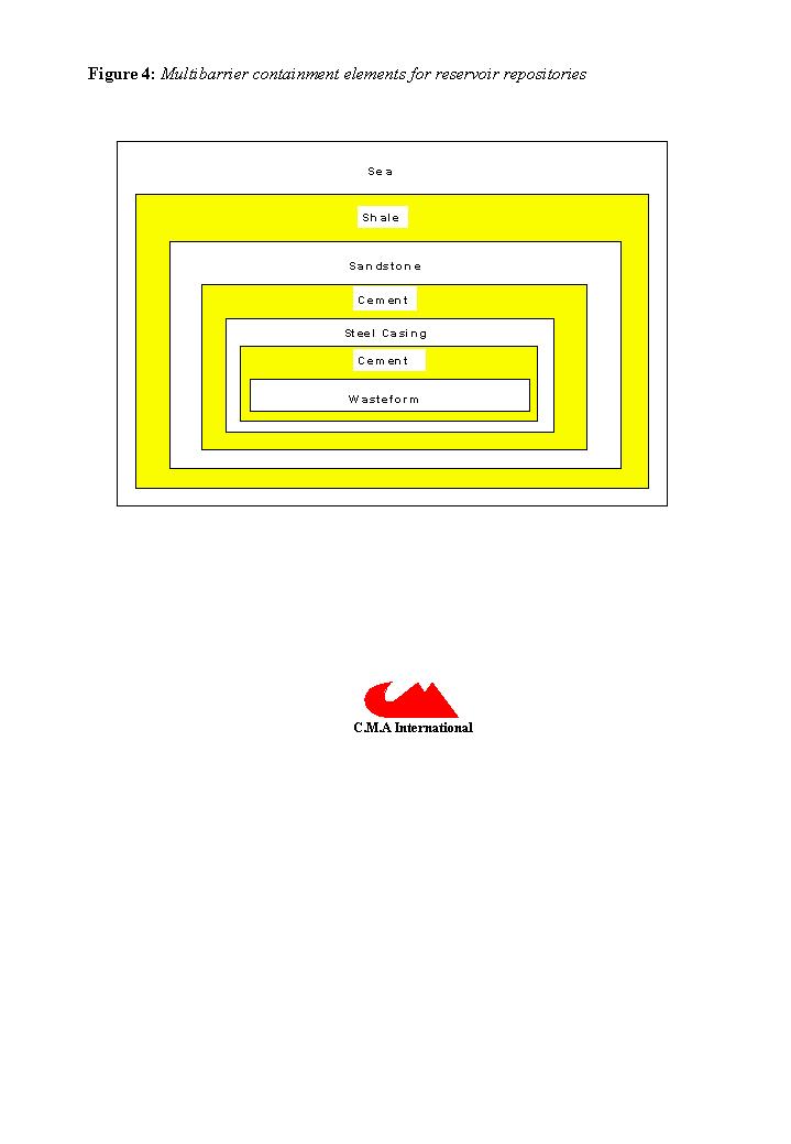
Emplacement of ceramic wasteforms into reservoir repositories can be achieved by the combination of offshore drilling and nuclear engineering technology. The wasteforms will be inserted into transportation sleeves, " transpacks", at the reprocessing plant and loaded into specially designed barges or ships. The transpacks are lowered to the seabed and the waste transferred to the repository using steel drillpipe where it is then sealed at depths of two or more kilometres the seabed. Maximum environmental radiological protection is combined with a minimum use of heavy and cumbersome materials, by utilising the shielding properties of seawater throughout the transfer operation. Multi barrier containment will be achieved by combination of engineered, geological and marine barriers, see figure 4.
Transportation methodology
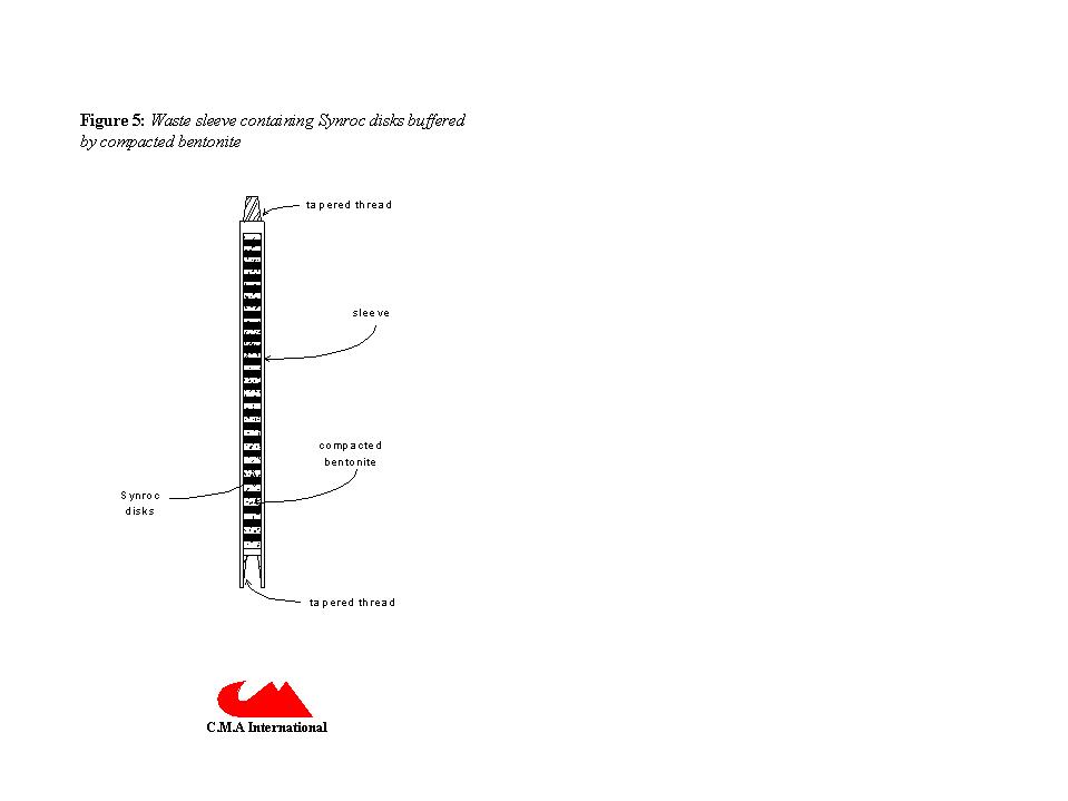
The wasteform is sealed inside a thin metal sleeve during the re-processing, this waste sleeve has threaded connections top and bottom, see figure 5. The waste sleeve will house the ceramic disks separated by compacted bentonite buffer disks. The waste sleeve is then inserted into the transpack.
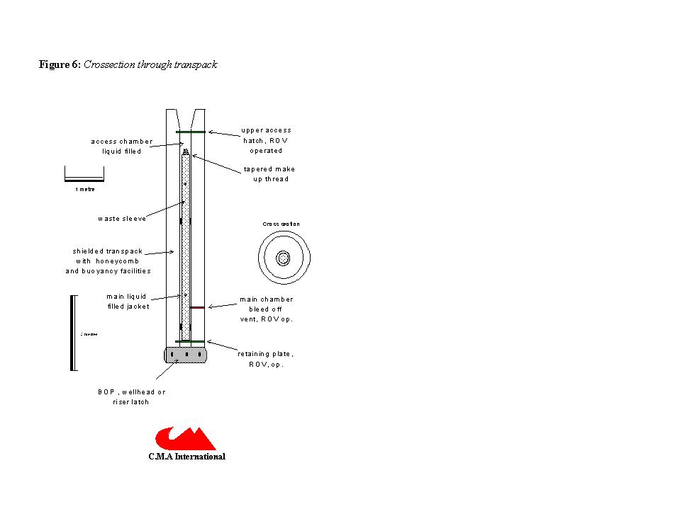
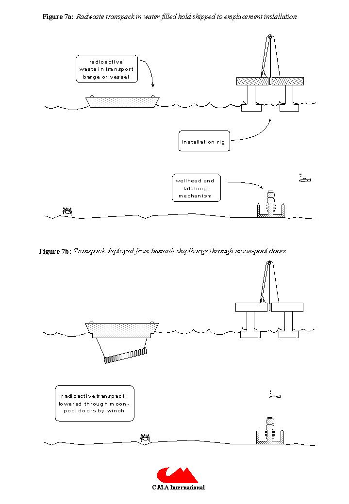
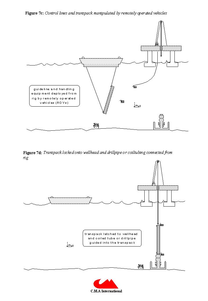
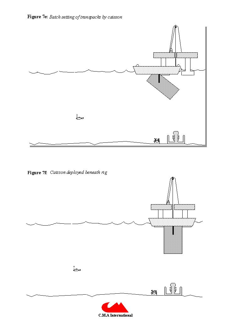
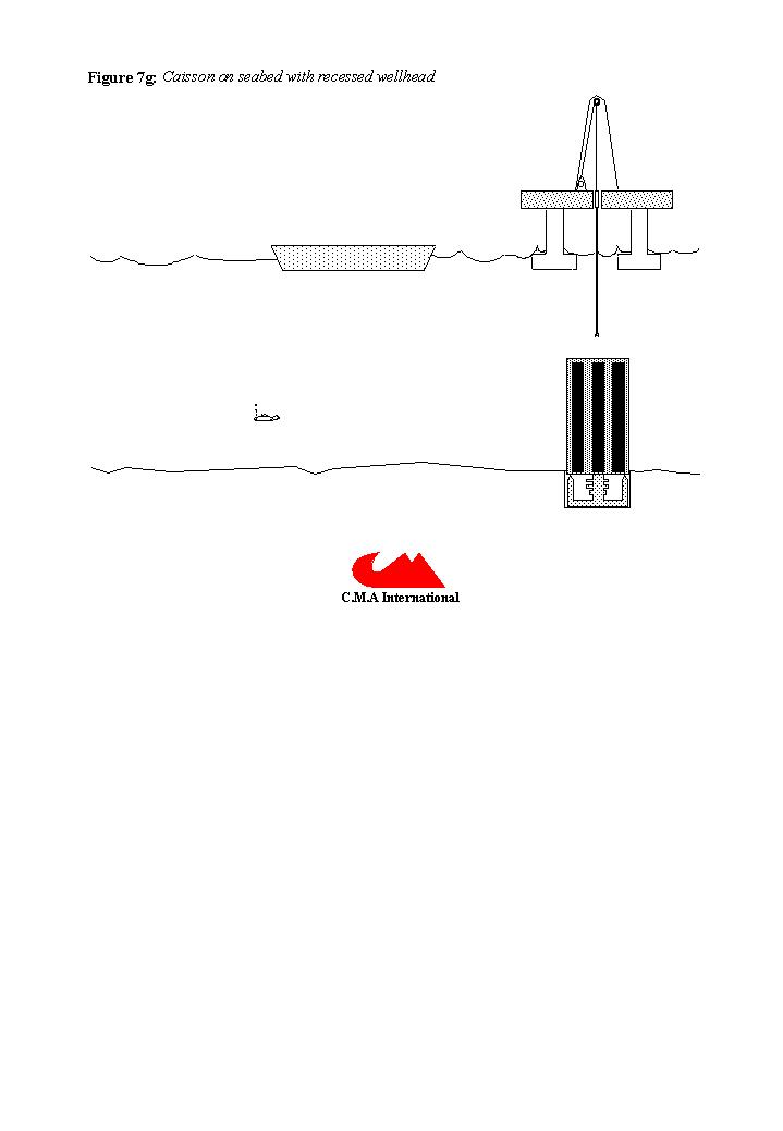
The transpacks will have an internal liquid jacket which will separate the waste sleeve from the transpack body and provide some buoyancy control, see figure 6. The transpacks will be transferred to the disposal location inside a barge or ship with a seawater filled hold. The hold will have doors in the hull through which the transpack is lowered over the wellhead, see figure 7a & 7b. The transpacks will be controlled by remotely operated vehicles (ROV), figure 7c & 7d. Efficiency and optimal safety will be achieved by batch setting multiple sleeves from a larger transpack or caisson, figure 7e & 7f that will be temporarily stationed on the seabed during emplacement operations, see figure 7g.
The Surface Handling System
HLW is too radioactive to bring onboard an emplacement vessel or installation so the waste sleeve is deployed from the seabed into the repository by drillpipe (DP) or spooled continuous steel tubing (CT), see figure 7d. The transpack will be locked into position at the wellhead, the liquid filled buoyancy jacket will be equalised and the top hatch opened. An assembly on the end of the drill pipe or coiled tubing (DP/CT) referred to as the running barrel, will be fed over the waste sleeve and engaged by a screw or clamp mechanism. The bottom hatch can then be opened and the running barrel will then be lowered into the borehole.
Reservoir pressure will be maintained at below hydrostatic pressure, allowing the overbalance pressure exerted by seawater to control the well, ensuring no direct connection with equipment and personnel at sea level. In this manner no reservoir fluid or radioactively contaminated drilling mud can come to the surface, ensuring safe operations at all times. Where it is necessary to recover any fluid returned from the well, these will be conveyed by flexible hose to the transport barge and returned to shore for processing.
Drilling methodology
The Running Assembly
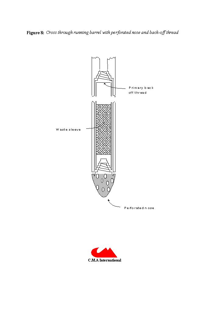
The lowermost waste sleeve will have a protective perforated nose, see figure 8, protruding from the throat of the lowermost running barrel which allows fluid in the borehole to flow through the annulus between the waste sleeve assembly and the running barrel. Multiple waste sleeves could be screwed together just beneath the seabed wellhead prior to emplacement thus minimising the number of times the DP/CT needs be run into the borehole.
After the running barrel has been lowered into the borehole, the combined waste sleeve assembly would be released from the running barrel by a primary coarse tapered back-off thread capable of holding the entire weight of the waste sleeve in air. This release system would be backed up by a series of emergency release mechanisms. The running barrels would also have a back-off system similar to the primary device on the top waste sleeve so the barrels too can remain downhole in the event of cementing problems or a total failure to release the waste sleeve assembly.
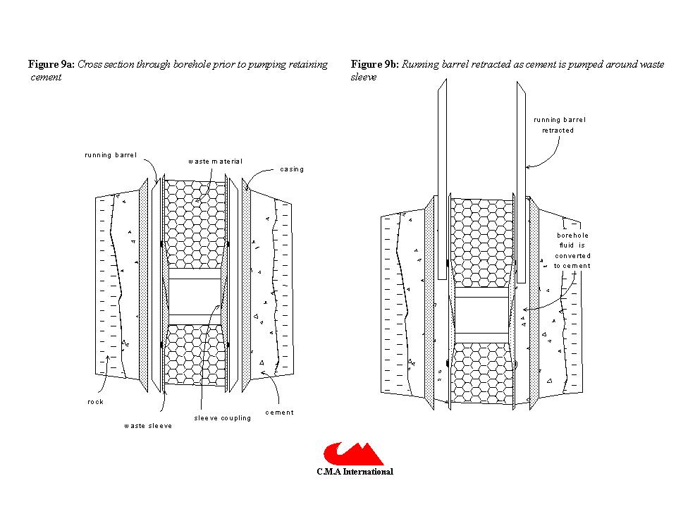
The Cementing Procedure
After the waste sleeve assembly is released, the running barrel is pulled back slightly and a retaining cement pumped downhole and around the sleeves whilst the barrel is progressively withdrawn. The cement will bond the waste container to the casing creating an impermeable lateral barrier. The running barrel is pulled out before the cement sets. More cement can then be circulated through the DP/CT and running assembly before pulling them out of the hole. Normal oil well cementing techniques will be used to achieve cement emplacement, see figure 9. Sintered refractory slag based drilling fluids which convert to cement without the need to circulate contaminated mud out of the borehole could also be used, particularly to create the containment barrier itself. Backfilling the reservoir repository will require a series of plugs similar to those proposed by the Swedish deep borehole disposal programme consisting of cement, bitumen and bentonite (SKB, 1992). Steel casing above the reservoir will also be removed to prevent potential pathways for radionuclides developing through the break down of the steel.
MANAGEMENT
Short term management
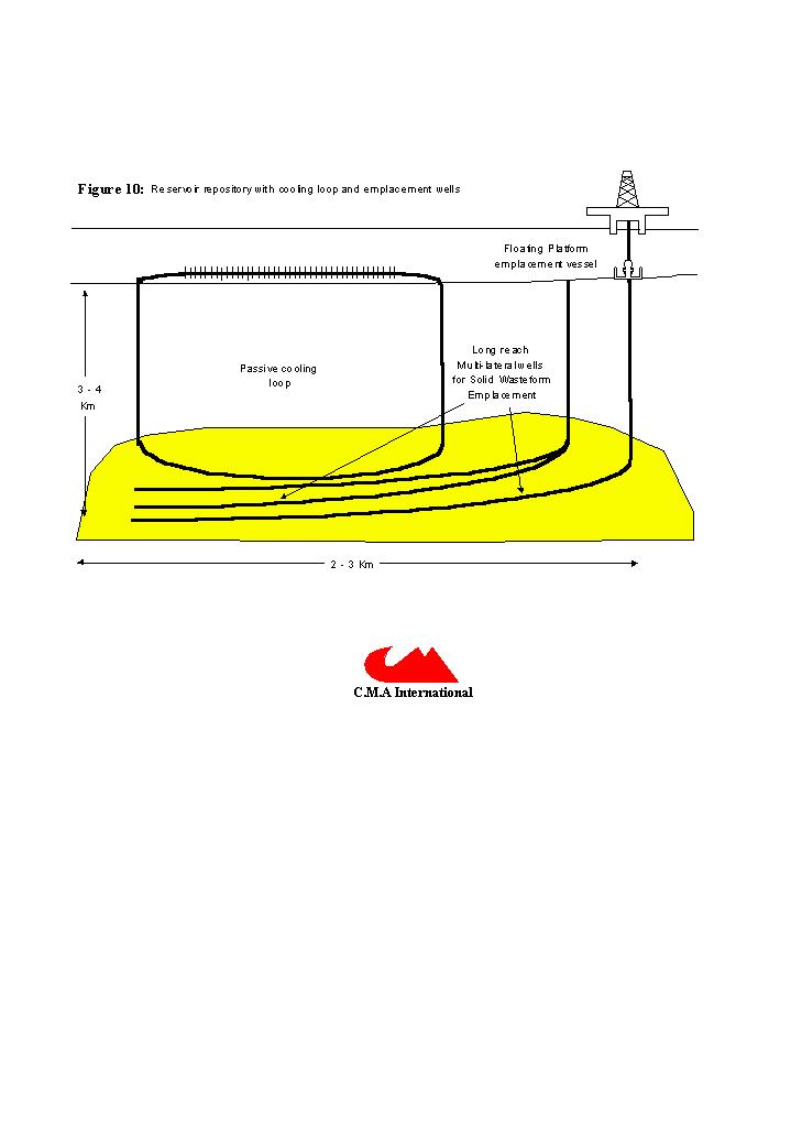
During emplacement operations and for a few years after closure, the reservoir would be cooled using passive convection circulation. This is achieved by drilling two connecting wells, possibly in a spiral pattern through the reservoir and by connecting them at the seabed where a one way valve system, pumps, radiators fins, intervention and monitoring equipment are connected, see figure 10. Drilling exploration wells in certain areas of the North Sea has shown that the natural geothermal gradient in the immediate vicinity of the well bore can be reduced by as much as 50% by circulating surface cooled fluid through a marine riser (personal experience). It should therefore be possible to maintain a steady heat flow in the vicinity of the wasteforms before final closure. With increased heat flow in the reservoir it could then be possible to inject fluids rich in silica and carbonate to promote enhanced diagenesis and occlude pore space in the vicinity of the wasteform. This process could also help encourage in-situ vitrification after closure, if the correct geochemical environment is engineered.
Long term management
Temperature in the repository on closure, after the passive cooling system is shut down and backfilled, will rise steadily. Initial reservoir temperature will start at between 40-100oC, this will raise by at least 60oC during the first 10 years after emplacement (Steadman, 1993). Temperature and pressure will rise until pore pressure reaches the minimum effective stress. Pressure will then leak off into enclosing shales and the reservoir will return to a lower pore pressure and fractures will heel until further heating renews the cycle. Gas will be generated by stripping hydrogen and oxygen atoms from pore water and residual hydrocarbon molecules through radiolysis. The gas will initially be retained in the reservoir, but the amount of retention will be governed by the elasticity of the reservoir. A reservoir with a known elastic response such as the Magnus Field (Watts, 1996), would have a modelable and calculable gas generation capacity governed by the mineralogy, porosity and fluid type. Convection circulation of reservoir fluids would ensure that the stress imposed by heating would be imposed uniformly on enclosing shales. The influence of individual fractures acting as weak points would not be an issue for a fluid reservoir that has already been pressure tested over millions of years.
Use of a titanate ceramic such as Synroc, theoretically allows a greater waste loading than glass because of its greater thermal stability. The melting point of Synroc is in excess of 1300oC, similar to basalt. Thus the wasteform itself should remain intact whilst the saturated sandstone host rock starts to dry out or fuse a lower temperatures. The host rock will dry out eventually melting and resulting in "in-situ vitrification" in the near field, (ORNL, 1992). A drying front, will propagate either parallel to the well bore, or preferentially along fractures. The more homogeneous the host, the greater chance that the melt will progress evenly around the wasteform. Homogenous melting will reduce the possibility of pockets of fissile material being preferentially re-deposited and possibly becoming critical, (Kastenberg, 1996).
CONCLUSION
The United Nations Convention on the Law of the Sea grants sovereign nations with coastal waters the right to exploit all resources above and below the seabed up to 200 nautical miles out from the littoral zone. This has enabled coastal nations to exercise fishing and mineral extraction rights over large areas of open water, areas known as their exclusive economic zones. The utilisation of exhausted oilfields for emplacement of radioactive waste is just another method of exploiting these resources. Reservoir disposal of HLW entails the exact placement of the wasteform at least 2 kilometres below the seabed in well lithified bedrock. The precise location of the wasteform will be known for all time and it is even conceivable using the technology described, that the wasteform could be retrievable if necessary. The terms of the London Dumping Convention were drawn up with the idea of preventing the pollution of the sea, from ILW or LLW in drums and penetrators containing HLW. These waste disposal methods cannot guarantee where the waste material will come to rest before it is actually jettisoned, neither can they guarantee the waste is not recovered accidentally or maliciously at a future date. Furthermore there are many areas of the seabed where the London Dumping Convention rules do not apply, for example in areas designated as suitable for munitions dumping. Use of reservoir repositories cannot be construed as "dumping" at sea. Unconditional acceptance of the terms of the London Dumping Convention prevents the best possible disposal methods being adopted (Nguyen, 1994), it stifles reasoned technical debate and assigns pariah status to those nations who have already conducted seabed dumping operation without considering the source of the all pollutants. Discharges from French and British reactors for example, can be identified in the Arctic, even though fuelled reactors have been dumped on the seabed and contaminated river waters continue to discharge into the Russian Kara Sea, (Beasley et al., Yiou et al., 1995).
The author recognises there may be better suited geological sites and climatic terrains outside the UK but presents here a solution for the disposal of the UK's HLW entire inventory which can be implemented within this countries judicial boundaries. Furthermore it could also be used for future arisings. This method is a passive system of storage, the emplacement technology presented here could also be adapted to facilitate active geological destruction by the introduction of waste into subduction zones outside UK waters where radionuclides can eventually be absorbed in the upper mantle, (Baird, 1997).
The potential for utilising the United Kingdoms declining hydrocarbon reservoirs as nuclear waste repositories will increase over the next two decades as more fields become depleted and abandoned. At present the oil business employs more geoscientists and drilling engineers than any other sector of British industry, as such this represents a rich resource in terms of facilities but most importantly knowledge and experience. These resources will decline as hydrocarbon reserves are exhausted, the opportunity for effective repository exploration and development will be gradually lost if the potential for this disposal method is not recognised now. The current UK HLW inventory can be incrementally disposed of, after a fifty year cooling lag has elapsed, utilising reservoir repository disposal. By use of discrete disposal sites rather than using one large site, means the HLW disposal and repository closure can be undertaken as soon as the cooled HLW comes out of the cooling vault.
ACKNOWLEDGMENTS
This paper has been the result of ideas, discussions and encouragement from the following people
Jess Cawley, Materials Research Institute, Sheffield, UK
Gary Couples, Department of Geology, University of Glasgow, UK
Robert Holst, Subsea Engineer, Aberdeen, UK
Miro Ivanovich, Enterprise Ltd., UK
David Nicholls, Odfjell Drilling & Consulting Company, Norway
Jon Petter Sargent, Norsk Hydro Produksjon as., Norway
Robert Turnbull, Environmental Resources and Technology Ltd., Edinburgh, UK
REFERENCES
Baird, J.R. 1997. The subductive Waste Disposal Method, A Method for Eliminating Excess Weapons Materials and High-level Waste. http://www.island.net/~bairdjr/
Barker, C., 1979. Organic Geochemistry in Petroleum Exploration. American Association of Petroleum Geologists, Education Course Note Series #10
Beasley, T.M., L.W.Cooper, J.M.Grebmeier & L.R.Kilius, 1995. Iodine-129 in Western Arctic Waters. Proc., Environmental Radioactivity in the Arctic ed. Cooke, A. & Strand, P., Oslo.
Bishop, W.P & C.D. Hollister, 1974. SeaBed Disposal - Where to Look. Nuclear Technology vol 24, pp 425-443.
Bushell, T.P. 1986. Reservoir geology of the Morecombe Field. in Brooks, J, J.C.Goff & B. Van Hoorn (eds) Habitat of Palaeozoic gas in NW. Europe. Geological Society, Special Publication, 23, pp189-208
Colter, V.S. & K.W. Barr, 1975. Recent developments in the Geology of the Irish Sea, in Woodward A.W. (ed) Petroleum and the Continental Shelf of NW. Europe. Applied Science Publishers
Cornford, C., 1986. Source Rocks and Hydrocarbons of the North Sea, in Glennie, K.W., ed. Introduction to the Petroleum Geology of the North Sea. Blackwell Scientific Publications
Dore, A.G. & E.R. Lundin, 1996. Cenozoic compressional structures on the NE Atlantic margin: nature, origin and potential significance for hydrocarbon exploration. Petroleum Geoscience, Vol 2, no. 4, pp 299-311.
Glennie, K.W., 1986. Introduction to the Petroleum Geology of the North Sea, Blackwell Scientific Publications
Jostons, A., 1994. Status of Synroc Development., in Proc., of the 9th Pacific Basin Nuclear Conference, Sydney.
Kastenberg, W.E., et. al. 1996, Considerations of Autocatalytic Criticality of Fissile Materials in Geologic Repositories. Nuclear Technology preprint, http://faraday.ee.latrobe.edu.au/~khorsell/anti-nukes/disposal/criticality.html
Lowe, D.R., 1982, Sediment gravity flows: II. Depositional models with special reference to the deposits of high density turbidity currents. Journal of Sedimentary Petrology, v 52, p 279-297.
Macaulay, C.I., Haszeldine, R.S, Fallick, A.E.,1992. Diagenetic porewaters stratified for at least 35 million years: American Association of Petroleum Geologists Bulletin, v76, no10, pp 1625-1634
Macy, F, 1993. Radiation Waste: Too Hot to Handle ?, An Iterview with Dr. Rustum Roy on How to Package Nuclear Waste. Nuclear Guardianship Forum, On the Responsible Care of Radioactive Materials, Issue #2, Spring 1993, p 11.
Malow, G., W. Lutze & R.C. Ewing, 1984. Alteration Effects and Leach Rates of Basaltic Glasses. Implications for the Long Term Stability of Nuclear Wasteform Borosilicate Glasses. Journal of Non-crystalline Solids. vol 67, no. 1-3, September 1984
Nguyen, T., 1994. High Level Nuclear Waste Disposal. http://www.nuc.berkeley.edu/thyd/ne161/nguyen/nguyen.html
Oversby, V.M. & A.E. Ringwood, 1981. Leach Testing of Synroc and Glass Samples at 85 and 200 degrees C. Nuclear & Chemical Waste Management, Vol 2, pp 201-206
ORNL, 1992. Tracer-Level Radioactive Pilot-Scale Test of In Situ Vitrification for Stabilisation of Contaminated Soil Sites at ORNL. ORNL/TM-12201. Oak Ridge National Laboratory, Oak Ridge Tennessee. pp 184
Parker, R.H., 1991. Problems in the development of artificial geothermal energy exploitation in Cornwall. Proceedings of the Ussher Society, 7, 316-320
Radioactive Waste Management Advisory Committee, 1994, Annual Report, HMSO.
Radioactive Substances Division, 1994. Review of Radioactive Waste Management Policy. Preliminary Conclusions. DOE, HMSO August 1994
Ringwood, A.E., V.M.Oversby, S.E.Kesson, W.Sinclair, N.Were, W.Hibberson & A.Major, 1981. Immobilisation of High Level Nuclear Reactor Wastes in Synroc: A current appraisal. Nuclear & Chemical Waste Management. Vol 2, pp 287-305
Ringwood, A.E., S.E.Kesson, K.D.Reeve, D.M.Levins & E.J.Ramm, 1988. Synroc. In: Radioactive Waste Forms for the Future, W Lutze & RC Ewing, eds, North-Holland, Amsterdam, pp 233-334.
Shanmugam, G., R.B. Bloch, S.M. Mitchell, G.W. Beamish, R.J. Hodgkinson, J.E. Damuth, T. Straume, S.E. Syvertsen and K.E. Shields, 1995. Basin-Floor Fans in the North Sea: Sequence Stratigraphic Models vs. Sedimentary Facies. AAPG Bulletin, vol 79, no. 4, pp 447-512.
Sivintsev, Y. & Kiknadze, O., 1995. Radioecological Danger of Long Lived Radionuclides in Nuclear Reactors, Dumped in Arctic. Proc., Environmental Radioactivity in the Arctic ed. Cooke, A.& Strand, P., Oslo.
SKB, 1992. Project on Alternative Systems Study (PASS): Final report. SKB report no. TR 93-04
Steadman, J.A.,1993. Underground Disposal of UK Heat-Generating Wastes: Repository Design Considerations. Radioactive Substances Division DOE, report no: DOE/RAS/93.005
Watts, G.F., D. Jizba, D.E. Gawith and P. Gutteridge, 1996. Reservoir monitoring of the Magnus Field through 4D time-lapse seismic analysis. Petroleum Geoscience, Vol 2, no. 4, pp 361-372.
Woodward, K. & C.D. Curtis. 1987. Predictive modelling for the distribution of production constraining illites. Morecombe Gas Field, Irish Sea, Offshore UK, in Brooks, J. & K.W. Glennie (eds) Petroleum Geology of N.W. Europe. Graham & Trottman, London, 205-215
Yiou, F., G.M. Raisbeck, Z.Q.Zhou, L.R.Kilius & P.J.Kershaw, 1995. Improved Estimates of Oceanic Discharges of 129I From Sellafield and La Hague. Proc., Environmental Radioactivity in the Arctic ed. Cooke, A. & Strand, P., Oslo.